Enhancement of Feed Drive Dynamics Using Additional Table Speed Feedback
Introduction
In machine tools, feed drives are used to produce a defined path of the tool relative to the workpiece, which is necessary for the particular process. An overview of typical design variants is given in [1]. For positioning axes, today, mainly electromechanical servo drives are used for reasons of good control performance and energy efficiency. Those are designed either as direct drives or with a mechanical gear, such as a ball screw. Both concepts have specific advantages and disadvantages, but they have in common that their electrical and mechanical parameters are defining and limiting the dynamic behavior of the entire feed system.
Targeted applications requiring high positioning dynamics
Dynamic behavior hereinafter is understood as the ability to follow a given reference variable as quickly and as precisely as possible (reference tracking) as well as insensitivity to external influences (disturbance rejection). An improvement of the dynamic behavior of the feed system promises a reduction of machining times through faster movements as well as enhanced process quality. In multi-axis machining, the weakest feed axis represents the limiting factor for the joint motion. In the past, different approaches from mechanical design to control engineering have been considered to improve the behavior, such as [2,3,4].
In general, the design of feed drives has to consider technical as well as economic requirements of the intended area of application; over dimensioning of drive components is avoided especially for serial kinematics, as it decreases the payload of consecutive axes. Consequently, the optimization of feed dynamics by means of design, control or actuator-based approaches outlines potential for increased process quality and efficiency in production engineering.
For the concept described below, targeted processes are those, in which dynamic parameters related to the motion (e.g. maximum acceleration) are primarily limitations, for example beam processing (laser cutting, water jet cutting, laser welding), high-speed cutting with little process forces or applications in additive manufacturing. In addition, dynamic limitations frequently are important parameters for applications in handling or industrial robotics. Although in most of these applications a multi-dimensional collaboration of several feed axes is implemented, there are cases in which only one axis has to execute dynamic motions.
Current limitations in path generation
Many machine tool applications require a specific path velocity \(v_f\) that is kept as constant as possible to guarantee static process conditions and a path guidance as exact as possible to create the specific workpiece geometry. However, these are competing requirements, since the acceleration capability of feed axes is limited by technical and economic aspects and abrupt acceleration changes also lead to strong excitation of the machine structure due to the reaction force of the drive. Discontinuous setpoint profiles, such as the corners of a contour or straight-circle transitions (shown schematically in Fig. 1) can therefore only be approximated during path planning within specified limits [5].
Established numerical controls offer different algorithms for generating a path that considers the requirements of the respective application. In the range of the mentioned discontinuities, either transition segments can be inserted (blending curves) or an exact stop can be planned, which, however, minimizes the path velocity. Furthermore, in order to reduce the excitation of the machine structure, acceleration and jerk are typically limited according to the machine capabilities [6].
Another approach, with parallels to the presented one, are redundant feed drive axes, which are shown for example in [7,8,9]. Here, several drives with very different dynamic behavior are combined so that the planned motion can be distributed to them. Often, long and rather slow axes are combined with fast ones having only a short travel range. The motion is then divided for example in a low frequency and a high frequency component. An exemplary procedure for controlling redundant drives is shown in [10].
The named approaches have in common, that they generally can improve the dynamic performance of feed drives but they still cannot overcome the underlying physical limitation—with a limited amount of actuator force, the velocity of the machine table can only be changed continuously. The proposed actuator concept shown in the next section aims to eliminate this limitation by using an alternative actuation method.
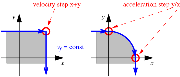
Path segments with discontinuities in the motion quantities velocity (left) and acceleration (right)
Hybrid feed drive concept with impact actuator
The concept shown here addresses both named aspects:
First, it increases the feed dynamics and thus improves the path guidance for profiles with discontinuous velocity or acceleration segments. Idealy, it enables step-wise velocity profiles, allowing the machine to exactly follow sharp corners which can only approximated with conventional drives. Second, it minimizes the excitation of the machine structure compared to high reaction forces occurring in standard feed drives at discontinuities in the path. This is achieved by using an inertia-based actuator, which distributes the reaction force over a broader interval and consequently reduces its influence.
For this purpose, a new functional concept is proposed, which is specially designed for the generation of discontinuous path profiles. It is able to abruptly change the state of motion by means of applying a defined mechanical momentum input onto the machine table. To the knowledge of the authors, no such approach has been applied on feed drives yet, so this paper aims at giving basic answers on applicability and potential performance. For this purpose, the table of the feed unit is equipped with an additional actuated mass with impact elements on both sides, which transmit kinetic energy from the actuator to the table. When the actuator mass is accelerated previously to a planned change in velocity, the resulting impact at one end of the actuator travel with a defined amount of kinetic energy leads to a sudden change in feed velocity. The machine table is only accelerated via the impact, so the machine frame is not subjected to the reaction force of the table. Since the acceleration of the actuator before and the deceleration after the impact occurs over a longer period of time, the reaction forces on and thus the excitation of the frame are significantly lower.
The aim of the ongoing work is to prove that this approach can be beneficial for following discontinuous contours, for example corners, with almost ideal geometry and constant path velocity.
At the same time, the inertia of the impact actuator could be used in a collision free mode to apply additive forces/accelerations on the table. Accelerating the actuator in the direction opposite to the table movement adds an additional force to the table, which does not need to be supported by the machine frame. As the travel distance of the actuator is short and it must be braked immediately, this can only be used for short force peaks. However, the focus of this paper is creating velocity steps and thus solely the impact-mode.
An evaluation of the performance is carried out by means of the resulting tracking error, which describes the deviation between the given, ideal discontinuous path and the real path. The reaction force on the machine structure can be quantified by means of the acceleration spectrum at the frame. Therefore, the machine frame is equipped with piezoelectric acceleration sensors in the three main directions, located at different positions. As the acceleration signal contains information on the occurring structural vibrations, a reduced excitation can thus be quantified.
Concept and simulation model of the impact actuator
Figure 2 shows the basic design model of a corresponding feed drive, which is examined within a multi-body simulation. To reduce the number of influence parameters as well as the coupling between several dynamic systems, a single feed axis system is considered. Based on the gained knowledge, multi-axes systems can be synthesized combining respective feed drives.
The additional actuator is arranged on the table of a base axis, actuated parallel to it. It has a defined stopper element on both sides where the impact occurs. The actuator mass is accelerated prior to a discontinuity so that the impact takes place at a defined point in time with the calculated velocity. With a suitable, synchronous control of the base drive and with an additional actuator, setpoint profiles can be designed more discontinuously or the planned geometry deviation can be reduced.
Although the actuator causes reaction forces during its acceleration and deceleration, which affect the base drive, they are distributed over a longer period of time compared to the period of momentum transfer. The base drive only has to support the actuator and compensate for static deviations and disturbing forces. This allows a weaker dimensioning than if it had to accelerate the machine table.
An inelastic collision with a corresponding coefficient of restitution equal to 0.9 is chosen for the approximation of the momentum transmission [11]. Since in reality the impact occurs as a very short time-continuous event, the progress of the contact force or penetration of the involved components can be estimated by means of a suitable model like described in [12].
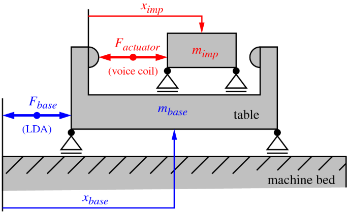
Multi-body structure of the proposed feed drive concept with additional actuator
Control structure
For the first validation, the drive structure is limited to one axis, which will be extended in ongoing work. A PPI cascade control is used for both the base drive and the additional actuator. Both have a direct measurement, so that the point in time of the collision and the impact velocity can be exactly met. To improve the stability for velocity steps and the control accuracy in general, both control structures are implemented with velocity feedforward control. The reaction force of the actuator on the base drive is compensated by force feedforward in the current control loop. Thus, no additional deviation is caused by actuator acceleration.
Setpoint path planning
From a particular velocity profile for the base drive with discrete, abrupt velocity changes, the boundary conditions for controlling the actuator can be derived: on the one hand the time point of the next velocity change \(t_{imp}\) is given, on the other hand the necessary velocity of the actuator mass before the impact \(v_{imp,0}\) can be calculated according to the principle of linear momentum. Here, the movement state of the base drive before the impact, the desired velocity change \(\varDelta v_{base}\), the masses of the actuator and the table, as well as the coefficient of restitution (as characteristic curve or single parameter) need to be known. The velocity of the actuator mass after the impact \(v_{imp,1}\) can also be calculated according to the principle of linear momentum. This results in the boundary conditions for the actuator profile for the times of the velocity steps of the base drive.
The motion of the actuator between two velocity changes principally can be arbitrary, but in order to minimize the reaction on the base drive, a minimum amount of actuator acceleration is advantageous. Here, curve segments, which can be differentiated at least twice, are used for the actuator motion path, for example cubic \(C^2\) splines or Bézier curves of degree 3.
In the present implementation, the motion profile is given in form of a table, defining discrete points in time with the target velocity to be achieved. Thus, the profile for the actuator can be completely calculated in advance.
An example of a motion profile for the base drive with the resulting actuator profile is given in Sect. 3.4.
Experimental verification
Testbed overview
The experimental verification of the functional principle is carried out on a single-axis testbed, which is shown in Fig. 3. The base drive uses a linear motor, while the actuator mass relative to the table is driven by a voice coil. By additional table masses, the mass ratios between table and actuator can be varied for the conducted experiments.
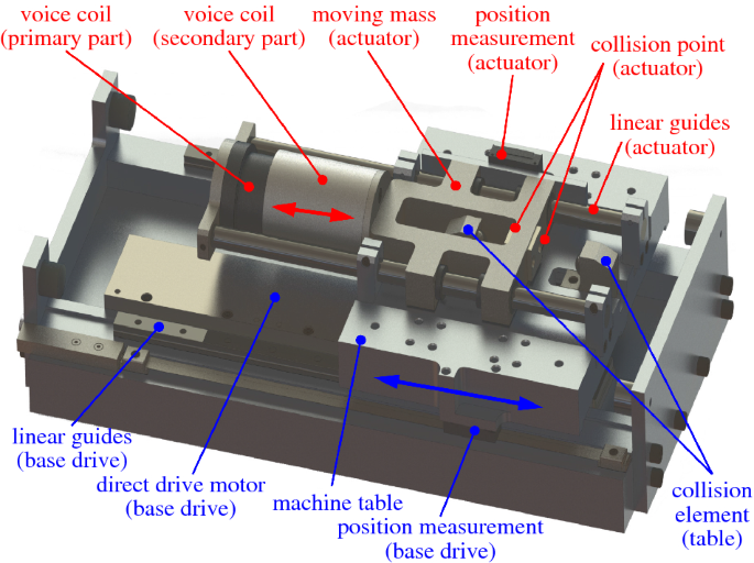
Functional components of the experimental setup
Momentum transfer characteristics
Since a discrete momentum input shall cause a specific change in motion state, knowledge regarding the transmission characteristics is crucial for the practical application as well as a sufficient reproducibility, which will be discussed later in this paper.
The calculation according to the principle of momentum conservation is only applicable if no external forces act on the participant bodies during the impact process. However, this is not true in the present arrangement with the two drives under control, as the respective controller will always attempt to compensate for an existing deviation between the given and the actual state of motion. Since the real impact process extends over a (very short) period of time, additive forces from both drives occur, which influence the momentum transmission. This is acceptable for the given application if the behavior is known and reproducible. Instead of the physical coefficient of restitution, an effective impact characteristic curve is used, which is calculated from the measured motion magnitudes under operation conditions and thus includes corresponding influencing factors.
To determine those characteristic curves, a series with 24 discrete quantities of the impact velocity in the range from 0.02 to 2.5 m/s is measured and analyzed, each with impact at the positive and negative direction. Also, the table mass is varied between 7.0 and 12.0 kg. The basic drive remains in position control with a constant setpoint. The peak velocity and acceleration attained in the impact are evaluated, the tests are based on an effective actuator mass of 4.0 kg.
Figure 4 shows the resulting peak velocity change at the table for the varied operation conditions. It can be seen that the amount of velocity change depends on both the table mass and the direction of impact (positive/negative). The former directly follows from the principle of momentum conservation; the latter is a result of different stiffness values of the presented actuator realization in both direction due to the asymmetrical design. The limit of the linear controllability, which is defined by the drive power, is reached at a peak impact velocity of 0.6 m/s. For a table mass of 7 kg, this corresponds to a velocity change of 0.45 m/s (positive direction) or 0.49 m/s (negative direction), for 12 kg corresponding to 0.32 or 0.39 m/s respectively. Of course, the applicability of those parameter ranges depend on the specific application and can be optimized within the actuator layout.
Figure 5 shows the corresponding peak table acceleration, which is calculated by the differentiation of the velocity value. Similar to the velocity curves, there is a linear correlation within the boundaries of the actuator performance. Compared to the peak acceleration capability of the base drive (25 resp. 43\(\hbox {m/s}^2\)), the actuator enables significant amounts of acceleration up to 800\(\hbox {m/s}^2\) for the short period of the velocity step occurring.
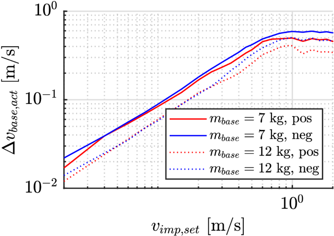
Maximum table velocity reached as a function of the specified impact velocity, double-logarithmic scale
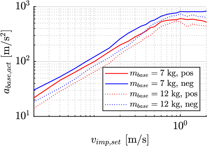
Maximum table acceleration reached as a function of the specified impact velocity, double-logarithmic scale
Reproducibility of impact conditions
To quantify the repeatability of the actuator principle, a profile with several impact velocities \(v_{imp,0,set}\) is evaluated for 15 repetitions. Table 1 shows the given nominal velocity step followed by mean value and standard deviation of the resulting velocity change at the table \(\varDelta v_{base}\) and the effective acceleration \(a_{base,eff}\). The maximum standard deviation is 2.4% for the velocity and 4.4% for the acceleration. The different amounts in the positive and negative direction correspond to the observed different impact characteristics for both directions. As there will be always deviations from the desired velocity change due to uncertainities in the system parameters, the remaining velocity error has to be compensated by the base drive.
Exemplary motion profile
To analyze the behavior of the hybrid feed drive system for a realistic application, an exemplary motion profile with discontinuities is defined by segments with stepwise constant velocity, as shown in Fig. 6. Based on the discrete velocity steps, a setpoint profile for the actuator is calculated, as shown in Fig. 7, where the upper and lower limits of the image correspond to the points of collision. It is remarkable, that the acceleration of the actuator is distributed over the full time interval between two impacts and so remains at lowest possible magnitude.
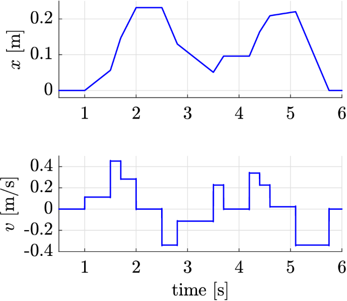
Exemplary motion profile used for validation
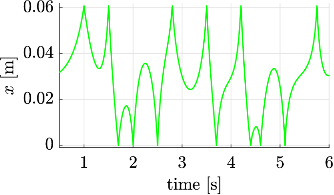
Corresponding actuator position path for validation profile
Comparison of tracking errors
The characterization of the guidance behavior along the given, discontinuous path is quantified by means of the tracking error. Figure 8 depicts the resulting tracking errors for the validation profile with and without activated actuator. It can be seen that the actuator is capable of reducing the tracking error significantly.
To compare the tracking errors for relevant operation states, its root mean square value was calculated over a period of 200 ms after different velocity changes. Figure 9 shows this mean value over the requested velocity step based on the experimental configurations with different base masses. While the tracking error with a neutral actuator increases as expected with growing velocity step, the error is reduced noticeable with active actuator.
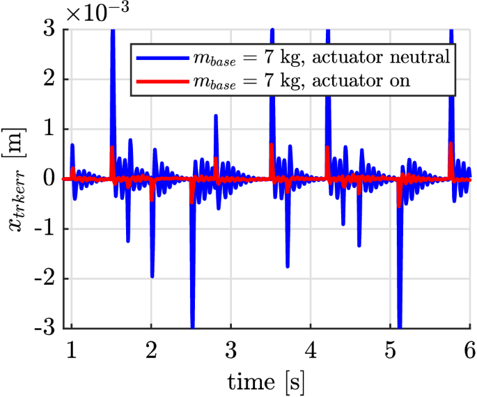
Resulting tracking errors for the given validation profile
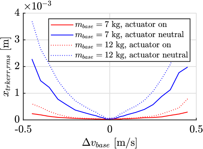
Cumulative tracking error for different velocity changes
Resulting structural vibration
While large resulting accelerations at the table are preferred for the mentioned applications with discontinuous profile, the opposite is desired for the machine frame or foundation. Depending on the parameters of the mechanical stiffness and damping, dynamic forces lead to static displacements and vibration. Those vibrations and displacements reduce the absolute accuracy and quality of the machining process. They can also increase the wear within the machine. An excitation in the frequency range of a mechanical eigenmode is particularly critical here, since significant vibrations can already be introduced with small excitation energies. Since the presented concept distributes the reaction forces of the drives over a longer period of time, their maximum amount can be reduced.
In order to quantify this effect, the present acceleration is measured on the frame of the testbed. Figure 10 shows a comparison of the determined frequency spectrum for all three spatial directions with (top) or without (bottom) activated actuator. The excitation of the first mechanical eigenfrequency (16.9 Hz) is clearly visible with neutral actuator. It can be seen that the conventional acceleration mode leads to significant vibrations in all spatial directions, which can be significantly reduced by activating the actuator. The desired effect (reduced vibration excitation of the frame with simultaneously increased acceleration) also occurs without other individual modes being significantly excited by the broadband excitation of the impact.
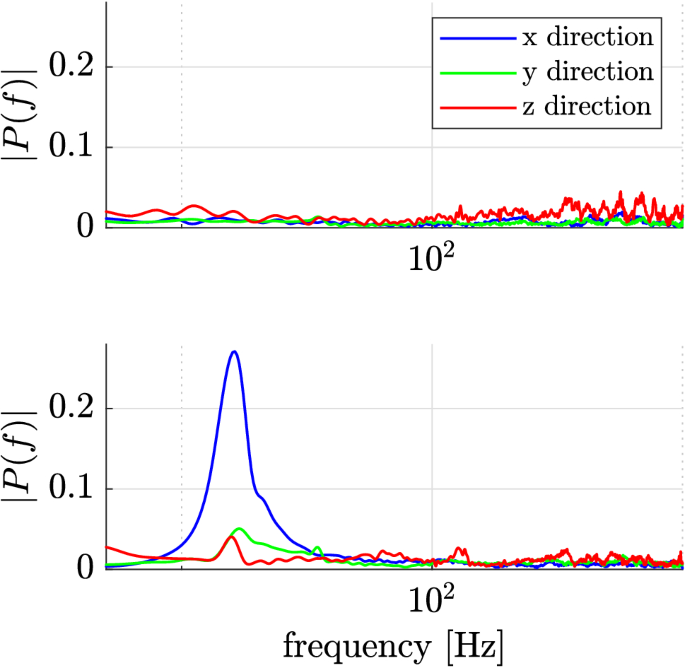
Resulting structural vibrations in different directions for active (top) and neutral (bottom) actuator
Results of the experimental validation
The experimental results confirm an improved behaviour of the feed drive with impact actuator for profiles with discontinuous velocity profiles. However, the improvements achieved require a detailed knowledge of the system parameters. The most important part are the variables for the calculation of the principle of linear momentum. An exact knowledge about the moving masses as well as the coefficient of restitution for the given change of velocity is essential. Under that precondition, the presented principle allows approximated velocity steps, which exceed the acceleration capabilities of other established methods.
Summary and outlook
Summary
It was shown that the proposed concept is basically a valid technology for the realization of feed drives for profiles with velocity steps. The results from the single axis proof of concepts can now be used to design and analyze more complex feed drive systems. Figure 11 depicts the realization of the testbed used for the experiments. Even if the velocity change occurs continuously due to the continuous time impact behavior caused by design and material properties, the steepness of the change considerably exceeds the capabilities of conventional feed drives.
At the same time, the kinetic energy required for the velocity change is distributed over a larger period of time and not concentrated in the shortest possible interval by the base drive—the peak force acting on the machine frame is reduced.
Compared to other hybrid feed drive concepts using conventional technology, the realization effort is similar while having the advantage of reducing the excitation of the mechanical eigenfrequency and allowing optimized lightweight designs.
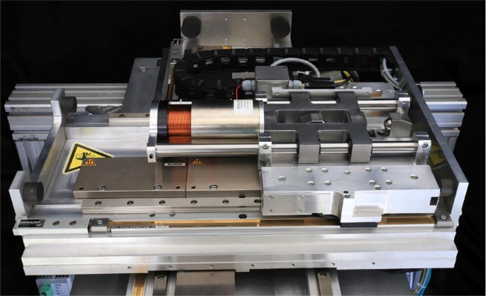
Overview on the feed drive test bed with additional actuator
Outlook
Within the present work, the general suitability of the concept could be proven and an overview of its sensitive parameters could be given. Besides, a large number of application-relevant questions remain, which are part of further research work. The most important one is the transfer to multi-axis kinematics, which allows to validate the basic motivation of cornering at constant path velocity. This requires an adequate combination of actuators as well as machine structures capable of transferring high accelerations to underlying axes. Other points of interest include optimization strategies for control as well as aspects like control integration and retrofitting.
Source: https://link.springer.com/article/10.1007/s11740-020-00950-3